1. Document Information
1.1. Abstract
This user guide shows how to get started with the MAVID-3M EVK.
1.2. Document Convention
| Icon |
Meaning |
Description |
 |
Note |
Provides information good to know |
 |
Caution |
Indicates situation that might result
in loss of data or hardware damage |
2. MAVID-3M EVK
Libre Wireless provides evaluation kits (EVK) for users to gain familiarity with our products and expedite their own design and development. User can connect to MAVID-
3M module through UART to configure the module.
MAVID-3M EVK is a development platform for Libre’s MAVID-3M module or solution.
MAVID-3M is a unique voice, AI, IoT platform or module with Wi-Fi 2.4GHz, BLE 5.0,
voice DSP (far field/near field detection, NR and AEC), application SoC and on-board
RAM and Flash (4MB each).
MAVID-3M EVK is a sophisticated kit with UART, SPI, I2C and GPIOs peripherals pin out
for developers to explore and implement their ideas in the area of AI, IoT and voice.
This development kit comes with compilation tool chain, user guides, data sheet, API
guides, Libre standard SDK with example applications for voice to device control (bulb
control, appliances control, motor control, etc.), demo mobile App (Android and iOS)
and support through FAQs. This makes the initial bring up and POC smoother for the
developers.
2.1. MAVID-3M EVK Block Diagram
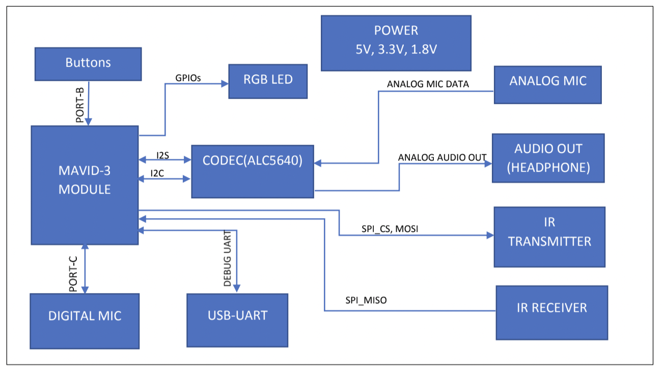
Figure 2.1: MAVID-3M EVK Block Diagram
2.2. MAVID-3M EVK Image
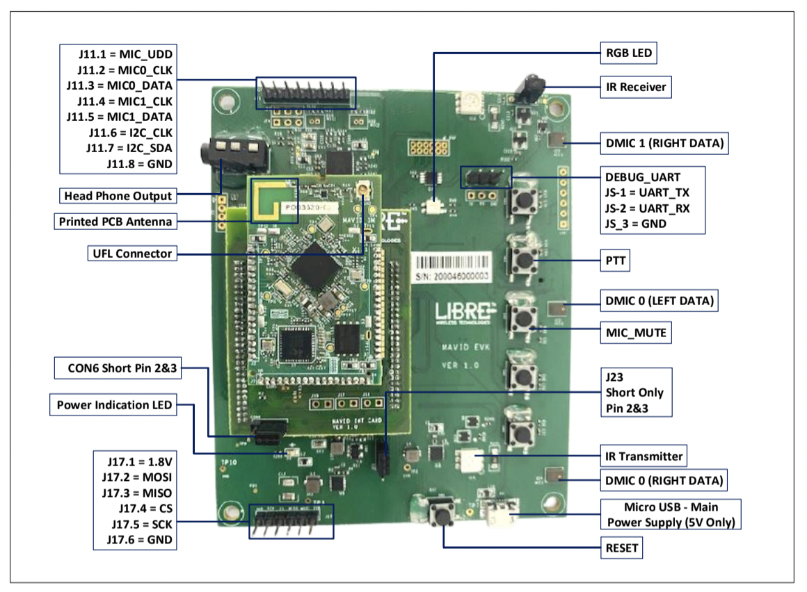
Figure 2.2: MAVID-3M EVK Image
2.3. What You Need
- MAVID-3M EVK
- 5V/2A power adapter
- Laptop Windows 8 or above/Linux
- Android or iOS mobile with Libre app
- Wi-Fi Router
- Remote
- Earphone or speaker with in-built speaker
- One Micro USB cable (+One optional)
2.4. Unboxing and Powering up MAVID-3M EVK
- MAVID-3M EVK Box contains 3 boards, namely MAVID-3M, Interconnect Card
and EVK Board.
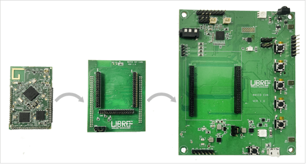
Figure 2.4-1: EVK Board Setup
- Connect all the 3 boards as shown in the below image to form a complete EVK
board setup. Please take care while connecting the boards, do not offset any pins
while connecting all the 3 boards into each other. Any offset may cause the
improper function of MAVID-3M EVK or the whole setup can get damaged.
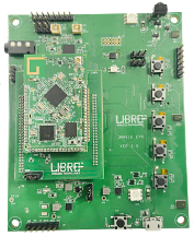
Figure 2.4-2: EVK Board Setup
- Power ON the board by supplying 5V adapter into the micro-USB connector
(Power). If supplying by some external methods, do not exceed more than 5.5V or
else it may damage the whole setup.
- Connect the micro-USB cable from laptop to USB-TTL connector provided in the
box.
- PC requirements:
- Windows 8 or above
- Linus/Ubuntu → Add the currently used Ubuntu OS version from
software team.
- Audio Jack: Connect 3.5 mm Audio connector cable to listen the audio outs from
Codec. Use earphone or speaker with in-built amplifier.
- Analog MIC: Connect Analog MICs to the MIC Connector when testing Analog MIC
into the board, else the connector can be left empty.
2.4.1. Jumper Connections
1. In the EVK board
- DVDD_IO can be of 1.8V and 3.3V. To make the connection, follow the following
connection:
- Short pin number 1 and 2 of J23 by a jumper to get DVDD_IO = 3.3V
- Short pin number 2 and 3 of J23 by a jumper to get DVDD_IO = 1.8V
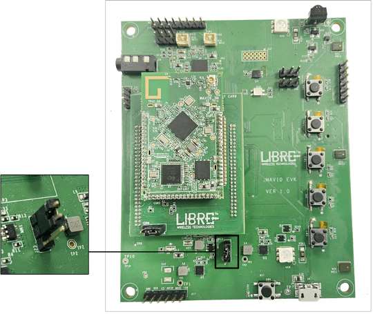
Figure 2.4.1-1: J23 Connector
- Acoustic Echo Cancellation (AEC) can be performed in two ways, one from
MAVID-3M side and another from Codec side. To make AEC from Codec do the
following jumper connections:
Short pin number 1 and 2 of J24 and short pin number 1 and 2 of J25 to get AEC
Left and Right from Codec respectively.
If AEC done from MAVID-3M side above jumper connection is not required.
- For analog MIC connection only short pin number 2 and 3 of J24 and short pin
number 2 and 3 of J25 to feed 2nd analog mic N & P to Codec respectively.
Figure 2.4-1: EVK Board Setup
2. In Interconnect card
- Short pin number 2 and 3 of CON6 to drive I2S_TXD from MediaTek
Short pin number 1 and 2 of CON6 to drive I2S_TXD from Knowles (Post Processed)
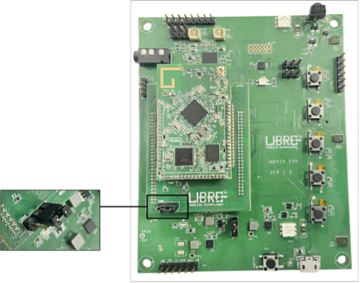
Figure 2.4.1-3: CON6 Connector
- Only in case of Analog MIC
- Short pin number 1 and 2 of J18 to connect LRCLK for I2S Format of Analog MIC Data
- Short pin number 1 and 2 of J17 to connect BCLK for I2S Format of Analog MIC Data
- Short pin number 1 and 2 of J19 to connect I2S Format of Analog MIC Data into Knowles
2.4.2. SPI Debug connector J17
| Connector Pin |
Signal |
| J17.1 |
1.8V |
| J17.2 |
SPI MOSI |
| J17.3 |
SPI MISO |
| J17.4 |
SPI CS |
| J17.5 |
SPI CLK |
| J17.6 |
GND |
2.4.3. I2C and MIC Connector J11
| Connector Pin |
Signal |
| J11.1 |
MIC VDD |
| J11.2 |
DM0 CLK |
| J11.3 |
DM0 DAT |
| J11.4 |
DM1 CLK |
| J11.5 |
DM1 DAT |
| J11.6 |
I2C SCL |
| J11.7 |
I2C SDA |
| J11.8 |
GND |
2.4.4. UART Connector J5
| Connector Pin |
Signal |
| J5.1 |
TX |
| J5.2 |
RX |
| J5.3 |
GND |
2.4.5. Class D Amplifier Connector
| Connector Pin |
Signal |
| J3.1 |
SPO_LP |
| J3.2 |
SPO_LN |
| J3.3 |
SPO_RN |
| J3.4 |
SPO_RP |
2.5. MAVID-3M Module
- A module consists of 2 RF friendly connection i.e., Wi-Fi & BT (BLE) supports 20MHz,
40MHz bandwidth in 2.4GHz band.
- Contains 4MB NOR Flash memory for program storage.
- Provides I2S MCLK of 12.288MHz.
- Contains VOICE over DSP for POST PROCESSING of Filtered Audio data.
- MAVID-3M pinouts are as below:
| Pin No. |
Connection |
Current Assigned |
| 1 |
3.3V |
3.3V |
| 2 |
3.3V |
3.3V |
| 3 |
GPIO4_B |
GPIO4_B |
| 4 |
GND |
GND |
| 5 |
GPIO0_B |
GPIO0_B |
| 6 |
GPIO9_B |
GPIO9_B |
| 7 |
GPIO10_B |
PWR_OFF |
| 8 |
CHIP_EN |
CHIP_EN |
| 9 |
GPIO13_B |
MIC_PWR_CTRL |
| 10 |
GND |
GND |
| 11 |
I2S_MCLK |
I2S_MCLK |
| 12 |
PORTA_FS |
I2S_LRCK |
| 13 |
PORTA_FS |
I2S_BCLK |
| 14 |
PORTA_DI |
PORTA_RXD |
| 15 |
GPIO1 |
I2S_TXD |
| 16 |
GPIO0 |
I2S_RXD |
| 17 |
PORTA_DO |
PORTA_TXD |
| 18 |
GPIO14 |
SPI_MISO |
| 19 |
GPIO16 |
SPI_CLK |
| 20 |
GPIO17 |
SPI_CS |
| 21 |
GPIO15 |
SPI_MOSI |
| 22 |
PORTB_FS |
PTT/SETUP |
| 23 |
PORTB_CLK |
MIC_PWR_ON/OFF |
| 24 |
PORTB_DI |
CHG_STATUS |
| 25 |
PORTB_DO |
PLAY/PAUSE |
| 26 |
GPIO_0(CHL) |
GPIO_0(CHL) |
| 27 |
GPIO_1(CHL) |
GPIO_1(CHL) |
| 28 |
PORTC_DO |
PORTC_DO |
| 29 |
PORTC_DI |
PORTC_DI |
| 30 |
PORTC_CLK |
PORTC_CLK |
| 31 |
PORTC_FS |
PORTC_FS |
| 32 |
COMMB_2 |
DSP_UART_TX |
| 33 |
COMMB_3 |
DSP_UART_RX |
| 34 |
GND |
GND |
| 35 |
COMMB_1 |
UART1_TX |
| 36 |
COMMB_0 |
UART1_RX |
| 37 |
GND |
GND |
| 38 |
NC |
NC |
| 39 |
1.8V |
1.8V |
| 40 |
VDD_IO |
VDD_IO |
| 41 |
VDD_IO |
VDD_IO |
| 42 |
GPIO1_B |
LED_RED |
| 43 |
GPIO15_B |
LED_GREEN |
| 44 |
GPIO18_B |
LED_BLUE |
| 45 |
RTC_EINT |
RTC_EINT |
| 46 |
GPIO14_B |
CODEC_RST |
| 47 |
GPIO8_B |
GPIO8_B |
| 48 |
BTVBAT |
BTVBAT |
| 49 |
VRTC |
VRTC |
| 50 |
GND |
GND |
| 51 |
GPIO18 |
ADC1 |
| 52 |
GPIO5 |
I2C0_SCL |
| 53 |
GPIO6 |
I2C1_SDA |
| 54 |
GPIO19 |
DEBUG_UART_RX |
| 55 |
GPIO20 |
DEBUG_UART_TX |
| 56 |
GND |
GND |
2.5.1. Buck Converter 5V to 3.3V and 1.8V
- The board contains buck converters to convert 5V to 3.3V and 5V to 1.8V.
- Switching frequency and Max current achievable are 1.4MHz and 2A respectively.
- Limits input to 5.5V Max.
2.5.2. ALC CODEC
- 2 Analog to Digital Converter with 94dBA SNR.
- 2 Digital to Analog Converter with 100dBA SNR.
- 3 Differential ended Analog MIC inputs.
- 3 Analog Audio output paths i.e., 2 Differential Class D speaker, Headphone and
Mono Output.
- I2S channels with up to 16 bits of I2S data for MCLK 12.288MHZ.
- I2C communication with address 0x38 (Write), 0x39 (Read).
2.5.3. D8 RGB LED
| State |
LED Indication |
| Ready/Idle State |
No Indication |
| Listening |
Cyan |
| Thinking |
Cyan and Blue - Alternating |
| Speaking |
Cyan and Blue - Pulsing |
| Notification Arrives |
Yellow - Burst |
| Notification Queued |
Yellow - Slow Pulse |
| Microphones Mute |
Red solid |
| Firmware Update |
Solid Magenta |
| Booting up |
White - blink |
| Wi-Fi Connected & Alexa not Connected |
Green blinking |
| Wi-Fi setup mode |
Multiple colors |
2.5.4. Digital MICs
- MEMS microphone with 65Db (A) SNR with a low distortion of 2.9% at 115dB SPL
and a flat frequency response between 20 – 20kHz.
- Max Supply = 3.6V, Max Clk freq = 4.8MHz.
2.5.5. Buttons functionality
| Switch# |
Short press Functionality |
Long press Functionality |
MAVID_3M PORT |
| SW3 |
PTT |
SETUP |
PORTB_FS |
| SW4 |
MUTE |
Reboot |
PORTB_CLK |
| SW5 |
Vol+ |
NA |
PORTB_DI |
| SW6 |
Vol- |
NA |
PORTB_DO |
| SW7 |
Play/Pause |
NA |
NA |
2.5.6. IR Transmitter & Receiver
- The IR Transmitter diode chip consist of 3 diodes which can be connected in series,
parallel, series - parallel based on requirement.
- Typical Forward voltage (Vf) = 1.35V for Forward Current (If) = 60mA. The diode can
be worked for Vf = 4.8V and If = 3A provided Pulse width <= 100usec and Duty cycle
<=1%.
- The IR transmitter diode on conducting has a wavelength of 940nm with
bandwidth of 65nm.
- Viewing angle of IR Transmitter is up to 140°.
- IR Receiver receive all the IR signals in range of 20kHz - 60kHz. Supply voltage typically, between 2.5V - 5.5V.
- Transmission distance of IR Receiver is 1.8 m typical with the directivity of 45°.